Working with metal part by turning or milling, the machined metal chip always entangling metal parts.
Normally, we can met following metal chip problems:
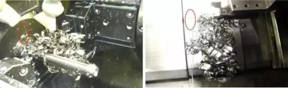
1.Metal Chip winding, workpiece can not be loaded and unloaded
2.Metal Chips must be removed after the machining finished.
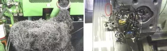
3.Metal Chip winding and outlet blockage
4.Metal Chip winding, tools life short and damaged easily.
Do you have any chip trouble? If so, it means that you are not familiar with the workpiece machining. If this continues, someone else has processed 100 pieces, and you may only have processed 90!
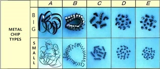
What are the shapes of metal chips?
What can we read from cut metal chips?
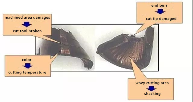
- if the machined metal chip area broken, damaged. That means the cut tool was broken.
- if the metal chip end has burr, it means the cutter tip damaged.
- the metal chip color shows the cutting temperature in machining process.
- if the metal chip has wavy cutting area, it means the cut tool was shacking in machining.
| Cutting temp.(℃) | metal chip colors | Cutting Temp.(℃) | metal chip colors |
| 200 | Canary yellow | 300 | Cyan |
| 229 | Yellowish brown | 320 | Pale blue |
| 240 | brown | 350 | Blue-grey |
Cut Metal Chip Principle and Direction
| Principle | Method | Note |
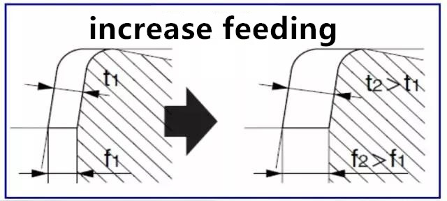
| metal chip become thick | increase feeding | roughness become bad |
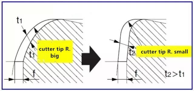
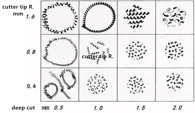
| metal chip become thick | cutter tip radius become small | roughness become bad damaged easily |
| metal chip become thick | Increasing Principal Deviation Angle | cutter tip strength become low |
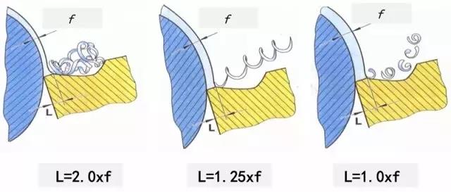
| Metal Crimp Reduced radius | use suitable metal chip breaker | cutting resistance is higher, cutter shacking |
WHAT ARE THE METHODS OF METAL CHIP BREAKING?
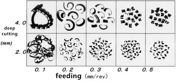
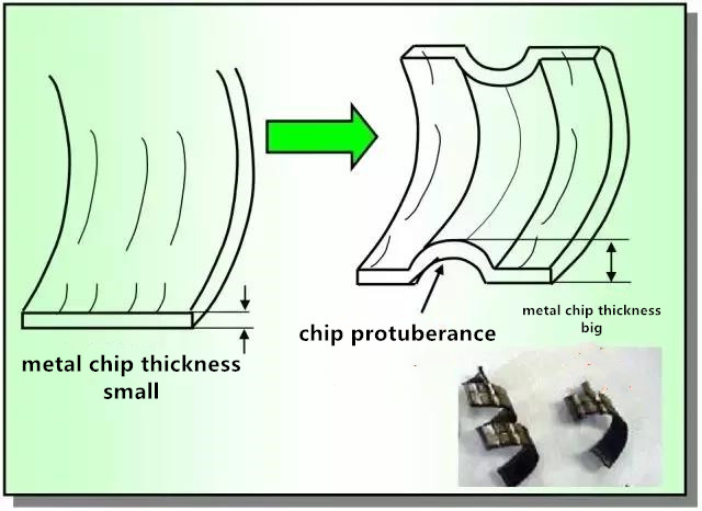
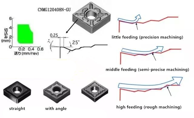
- Increasing chip thickness after feeding is beneficial to chip breaking
2.The radius of cutter tip roundness decreases and chip thickness increases.
3.Reduce the front corner
Chip compression ratio = hc/h
- The bigger the compression ratio is, the easier chip breaking will occur. At the same time, the cutting resistance will also increase.
- Compression ratio is related to linear velocity Vc. When Vc decreases, compression ratio increases, so reducing linear velocity is also beneficial to chip breaking.
- The decrease of the front angle, the large chip deformation and the increase of the compression ratio are beneficial to chip breaking.
Use sharp edge cutting tool
As photo show, under the same feed conditions, the blade has sharp edges, which is conducive to metal chip breaking.
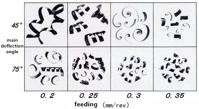
Increasing the main deflection angle and thicker chips are beneficial to chip breaking

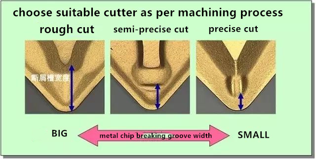
Protruding chip breaking groove to promote chip breaking
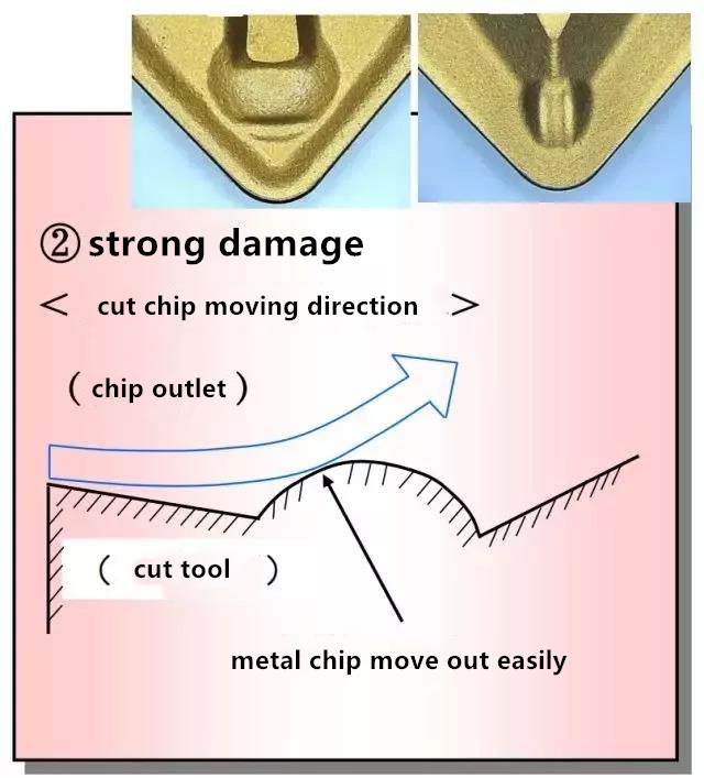
Scraping the surface of the chip from the protuberance of the chip breaking groove produces a dent—-Significant increase in chip thickness—Promoting chip breaking is highly damaging
The contact area with chips decreases and the chips discharge smoothly due to smooth contact with protrusions—Less damage to cutting tools
Reduction of Chip Curling Radius
More information about NC machining, CNC machining services and metal machined part, contact with us: cnkylt@aliyun.com +008615195010186
KYLT CNC Machining Services:
KYLT CNC Precision Machined Parts:
More information about Machining Technology:
评论
发表评论