There are many kinds and specifications of CNC machine tools, and the classification methods are different. Generally, it can be classified according to the following four principles according to functions and structures:
classification according to the control track of machine tool movement
(1) CNC MACHINE TOOL CONTROLLED BY POINT AND POSITION
Point control only needs to control the moving parts of machine tool to move from one point to another.
(2) LINEAR CONTROL CNC MACHINE TOOL
(3) CONTOUR CONTROL CNC MACHINE TOOL
Contour control CNC machine tool is also called continuous control CNC machine tool. Its control feature is that it can control the displacement and speed of two or more motion coordinates at the same time.
The corresponding numerical control device is called contour control numerical control system.
ACCORDING TO THE NUMBER OF COORDINATE AXES IT CONTROLS, IT CAN BE DIVIDED INTO THE FOLLOWING FORMS:
1. two axis linkage
2. two axle half linkage
3. three axis linkage:
Three axis linkage is generally divided into two categories: One is x / Y / Z three linear coordinate axis linkage, more used for CNC milling machine, machining center, etc. The other is to control not only the coordinates of two lines in X / Y / Z, but also the axis of rotation around one of them.
4.four axis linkage: simultaneously control X / Y / Z three linear coordinate axes and a rotation coordinate axis.
5.five axis linkage: in addition to controlling the linkage of X / Y / Z ﹣ three axes, it also controls the two axes of a, B and C that rotate around these linear axes, forming the simultaneous control of five axes linkage. At this time, the tool can be set in any direction of space.
Classification according to servo control mode
(1) OPEN LOOP CONTROL CNC MACHINE TOOL
The feed servo drive of this kind of machine tool is open-loop.
(2) CLOSED LOOP CONTROL MACHINE TOOL
The feed servo drive of this kind of NC machine tool works in the way of closed-loop feedback control.
According to the difference between the installation position of the position feedback detection element and the feedback device used, it can be divided into two control modes: full closed loop and half closed loop.
(3) HYBRID CONTROL CNC MACHINE
The characteristics of the above control methods can be selectively centralized to form a hybrid control scheme.
Classification according to the functional level of CNC system
According to the function level of CNC system, CNC system is usually divided into three categories: low, medium and high.
(1) METAL CUTTING
Refers to the use of turning, milling, collision, reaming, drilling, grinding, planing and other cutting processes of CNC machine tools. It can be divided into the following two categories.
① general CNC machine tool
② machining center
(2) METAL FORMING
It refers to the numerical control machine tool with extrusion, punching, pressing, drawing and other forming processes, commonly used including numerical control press, numerical control bending machine, numerical control bending machine, numerical control spinning machine, etc.
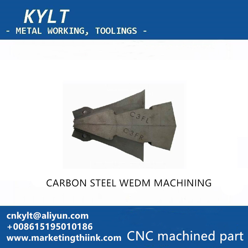
(3) SPECIAL PROCESSING
It mainly includes CNC WEDM, CNC EDM forming machine, CNC flame cutting machine, CNC laser processing machine, etc.
(4) MEASUREMENT AND DRAWING
There are mainly three coordinate measuring instruments, CNC tool setting instruments, CNC plotter, etc.
KYLT Precision CNC machining services (milling & turning service), Fast prototyping, Fixture/Jig/Tooling making, Aluminum die casting & plastic injection parts. Email:cnkylt@aliyun.com +008615195010186
KYLT CNC Machining Services:
KYLT CNC Precision Machined Parts:
More information about Machining Technology:
评论
发表评论