When design machine parts / prototypes by 2D engineering method, we can adopt simplified drawing method:
1.When the object (mechanical part) has several identical structures (teeth, slots, etc.) and distributes according to certain rules, only a few complete structures need to be drawn. The rest are connected by fine lines, and the total number of structures is indicated.
Mechanical part Examples of Simplified Drawing of Mechanical Drawings :
Examples of Simplified Drawing of Mechanical Drawings for Same Structure and Simplified Drawing
Same Structure and Simplified Drawing
2.A number of holes with the same diameter and regular distribution (round holes, screw holes, sinks, etc.) can be drawn only one or several, the rest can only be represented by the center line, and the total number of holes should be indicated when the size of holes is marked in the figure.
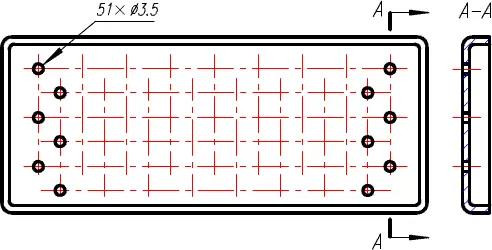
Simplified Drawing Method for Regularly Distributed Holes
3.The reticulated and knitted parts of nets, knitted fabrics or objects can be drawn by means of fine lines near the contour lines, and the specific requirements of these structures can be indicated on the drawings or technical requirements.
NC Turned Aluminum parts with knurled
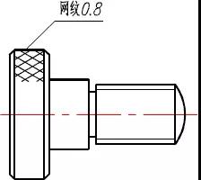
Simplified reticulation
4.When the graphics can not fully express the plane, they can be represented by plane symbols (two intersecting solid lines).
CNC Turning and milling part samples:
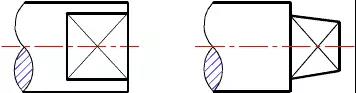
Representation of Plane by Plane Symbols
5.Small structures on objects can be simplified or omitted if they are clearly expressed in one figure. Two small circles are omitted from the main view and the intersection line is simplified from the top view.
Precision CNC turned part with CNC machining structure simplified drawings:
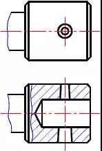
Simplification of Small Structure
6.In the absence of misunderstanding, small rounded corners on objects, small chamfered edges or small chamfered corners of 45 degrees on sharp edges may be omitted without drawing, but they must be specified in size or specified in technical requirements.
Simplified drawing examples show for CNC Milling machining and Turning parts chamfer:
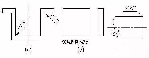
Small rounded corners, small chamfered corners and 45 degrees small chamfered corners can be omitted without drawing.
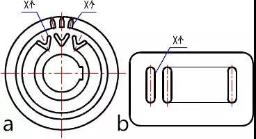
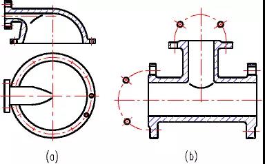
7.The uniformly distributed holes on cylindrical flanges and similar parts can be represented by the following figure method.
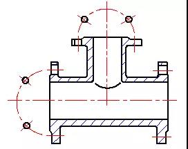
Simplified Drawing Method of Uniform Distribution of Holes on Cylindrical Flange
8.A circle or arc with an inclination less than or equal to 30 degrees from the projection surface can be replaced by a circle or arc.
Aluminum Prototype Example for Simplified Drawing of Mechanical Drawings
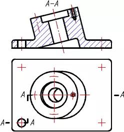
Projection of a circle less than or equal to 30 degrees
9.When the shapes of long objects (axes, rods, profiles, connecting rods, etc.) along the length direction are consistent or vary according to certain rules, they can be shortened and drawn after disconnection, but the dimensions are still marked according to the actual length.
Die casting part or CNC turning part sample for Simplified Drawing of Mechanical Drawings
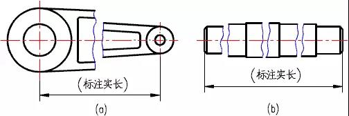
Disconnection Drawing Method for Longer Machine Parts
10.Structures with small slopes on objects. If they are clearly expressed in a figure, other figures can be drawn at the small end.
Structures with small slopes are drawn at small ends.
11.The intersection line of the orifice can be replaced by a straight line.
CNC turned part with drill hole example:
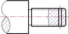
Intersection line is simplified to straight line
12.The transition line in the figure should be drawn according to the figure below. Without causing misunderstanding, transition lines and intersecting lines allow simplification, such as replacing non-circular curves with arcs or straight lines.
KYLT Precision CNC machining services (milling & turning service), Fast prototyping, Fixture/Jig/Tooling making, Aluminum die casting & plastic injection parts. Email:cnkylt@aliyun.com +008615195010186
KYLT CNC Machining Services:
KYLT CNC Precision Machined Parts:
More information about Machining Technology:
评论
发表评论