Common terms of numerical control system (NC, CNC MACHINE)
Increment pulse coder
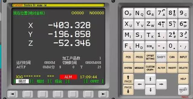
The rotary position measuring element is installed on the motor shaft or ball screw. When rotating, it sends out equal interval pulse to indicate displacement. Because there is no memory element, it can not accurately represent the position of the machine tool. Only when the machine tool returns to zero and the zero point of the coordinate system of the machine tool is established, can the position of the worktable or tool be indicated. It should be noted that there are two ways to output the signal of incremental encoder: serial and parallel. Some CNC systems have serial interface and parallel interface.
Absolute pulse coder
The rotary position measuring element has the same function as incremental encoder and memory element, which can reflect the actual position of machine tool in real time. After the machine is turned off, the position will not be lost. After the machine is turned on, it can be put into operation immediately without returning to zero. As with the incremental encoder, attention should be paid to the serial and parallel output of pulse signals.
Orientation
In order to perform spindle positioning or tool change, the spindle of the machine tool must be positioned at a certain turning angle in the circular direction of rotation as the reference point of action. Generally, there are four methods as follows: orientation by position encoder, orientation by magnetic sensor, orientation by external one turn signal (such as proximity switch), and orientation by external mechanical method.
Tandem control
For large worktable, when the torque of one motor is not enough to drive, two motors can be used to drive together. One of the two shafts is the driving shaft and the other is the driven shaft. The driving shaft receives the control command from CNC, and the driven shaft increases the driving torque.
Rigid tapping
The tapping operation is realized by the rotation of the spindle and the synchronous operation of the tapping feed shaft instead of using the floating chuck. When the spindle rotates for one revolution, the feed of the tapping shaft is equal to the pitch of the tap, which can improve the accuracy and efficiency. Wechat for metal processing, good content, worthy of attention. In order to achieve rigid tapping, the spindle must be equipped with a position encoder (usually 1024 pulses / revolution), and it is required to prepare a corresponding ladder diagram and set the relevant system parameters.
Tool compensation memory A, B, C
Generally, the available parameters of the tool compensation memory are set to any one of type A, type B or type C. The external performance is: type A does not distinguish the geometric compensation and wear compensation of the tool. Type B is to separate geometry compensation from wear compensation. Type C not only separates the geometry compensation from the wear compensation, but also separates the tool length compensation code from the radius compensation code. The length compensation code is h and the radius compensation code is d.
DNC operation
It is a working mode of automatic operation. The CNC system or computer is connected by RS-232C or RS-422 port. Themachining program is stored on the hard disk or floppy disk of the computer, and is input to the CNC section by section. Each input section of the program is processed section by section, which can solve the limitation of the memory capacity of the CNC.
Advanced preview control
The function is to read in several program segments in advance, to interpolate the running track and to preprocess the speed and acceleration. In this way, the following error caused by acceleration and deceleration and servo lag can be reduced, and the cutter can follow the part contour precisely at high speed, so that the machining accuracy can be improved. Pre reading control includes the following functions: linear acceleration and deceleration before interpolation; automatic deceleration of corners, etc.
Polar coordinate interpolation
Polar coordinate programming is to change the Cartesian coordinate system of the two linear axes into the coordinate system of the horizontal axis as the linear axis and the vertical axis as the rotation axis, and use this coordinate system to program the non-circular contour. It is usually used for turning straight grooves or grinding cams on a grinder.
NURBS interpolation (m)
In order to ensure the accuracy, the non-uniform rational B-spline function (NURBS) is used to describe the sculpture surface and curve. Wechat for metal processing, good content, worthy of attention. Therefore, the CNC system has designed the corresponding interpolation function, so that the expression of NURBS curve can directly command CNC, avoiding the machiningof complex contour surface or curve by the approach of small line segments.
Automatic tool length measurement
The contact sensor is installed on the machine tool, and the measuring program of the tool length (g36, G37) is compiled like the machining program, in which the offset number of the tool is specified. The program is executed in automatic mode to make the tool contact with the sensor, so as to measure the length difference between the tool and the reference tool, and automatically fill the value into the offset number specified in the program.
CS contour control
CS contour control is to change the spindle control of lathe into position control to realize the positioning of the spindle according to the rotation angle, and it can be interpolated with other feed shafts to process the workpiece with complex shape.
Manual absolute on / off
It is used to determine whether the coordinate value manually moved after feed pause is added to the current position value of automatic operation during automatic operation.
Manual handle interruption
By shaking the hand wheel during automatic operation, the moving distance of the moving shaft can be increased. Used for travel or size correction.
Axis control by PMC
Feed servo axis controlled by PMC (programmable machine controller). The control command is programmed in the program of PMC (ladder diagram). Because of the inconvenience of modification, this method is usually only used for the feed axis control with fixed movement.
CF axis control (T Series)
In the lathe system, the rotation position (angle) control of the spindle is realized by the feed servo motor like other feed axes The axis is linked with other feed axis for interpolation, and any curve is processed. (common in older lathe systems)
Follow up
When the servo is off, emergency stop or servo alarm, if the mechanical position of the worktable moves, there will be position error in the CNC position error register. The position tracking function is to modify the position of the machine monitored by the CNC controller, so that the error in the position error register becomes zero. Of course, whether to perform position tracking should be determined according to the actual control needs.
Simple synchronous control
One of the two feed shafts is the driving shaft, the other is the driven shaft. The driving shaft receives CNC motion instructions, and the driven shaft follows the driving shaft, so as to realize the synchronous movement of the two shafts. CNC monitors the moving position of two shafts at any time, but does not compensate for the error of the two shafts. If the moving position of the two shafts exceeds the set value of the parameter, CNC will give an alarm and stop the movement of each shaft at the same time. This function is commonly used in the double axle drive of large worktable.
Three dimension tool compensation (m)
In the process of multi coordinate machining, the tool can be offset compensated in three coordinate directions. It can realize the compensation of side machining with cutter and the compensation of end machining with cutter.
Tool nose radius compensation (T)
In order to turn accurately, the radius of the tool tip arc is compensated according to the cutting direction and the relative orientation between the tool and the workpiece.
Tool life management
When multiple tools are used, the tools are grouped according to their service life, and the use order of tools is preset on the CNC tool management table. When the tool used in machining reaches the service life value, the next tool of the same group can be replaced automatically or manually, and the next tool of the same group will be used after the tool of the same group is used up. Whether it is automatic or manual, the ladder diagram must be compiled for tool replacement.
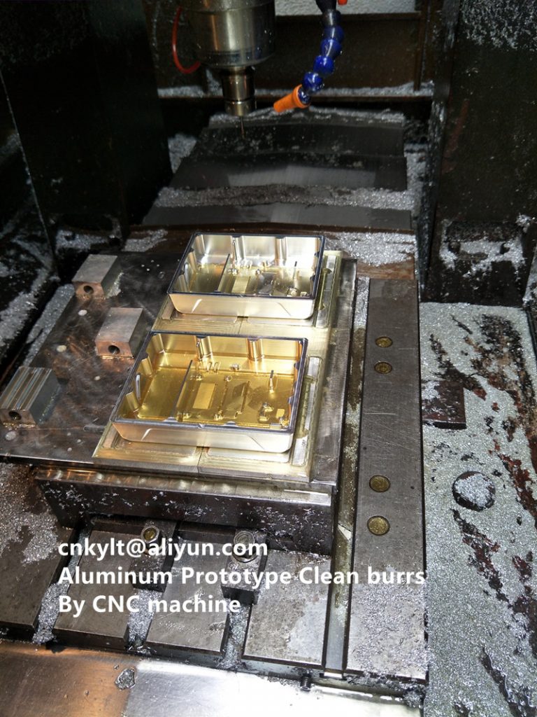
KYLT Precision CNC machining services (milling & turning service), Fast prototyping, Fixture/Jig/Tooling making,Aluminum die casting & plastic injection parts. Email:cnkylt@aliyun.com +008615195010186
KYLT CNC Machining Services:
KYLT CNC Precision Machined Parts:
More information about Machining Technology:
评论
发表评论