跳至主要内容

MILLING SKILLS

This article stated 17 application skills of milling.

What is milling?

Milling is to fix the blank and use a high-speed milling cutter to cut out the required shape and features. Traditional milling is mostly used for milling simple shapes / features such as profiles and grooves. CNC milling machine can process complex shape and features.
Milling and boring machining center can be used for three-axis or multi axis milling and boring machining, for machining, mold, inspection tool, fixture, thin-walled complex surface, artificial prosthesis, blade, etc. When choosing the content of NC milling, we should give full play to the advantage and key role of NC milling machine.
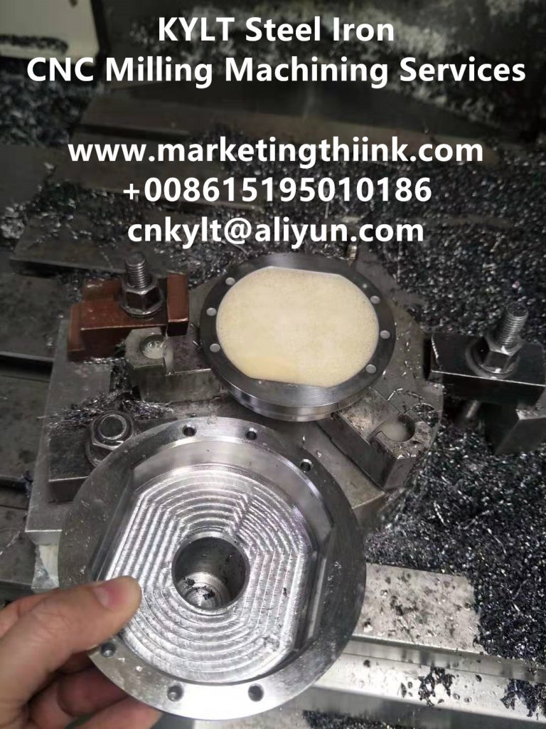
KYLT Steel Iron CNC milling part
In the actual production of milling, including machine tool setting, workpiece clamping, tool selection and other application skills, this issue briefly summarizes 17 key points of milling, each of which is worth your in-depth grasp.

POWER CAPACITY

Check the power capacity and rigidity of the machine to ensure that the machine can use the required milling cutter diameter.

WORKPIECE STABILITY

Workpiece clamping conditions and considerations.

OVERHANG

During machining, the tool overhang on the spindle shall be as short as possible.

SELECT THE RIGHT GEAR PITCH OF MILLING CUTTER

Use the correct pitch of milling cutter suitable for the working procedure to ensure that there is not too much blade involved in cutting, otherwise vibration will be caused.

CUTTING KNIFE

For narrow workpiece or gap milling, make sure that there is sufficient blade cutting.
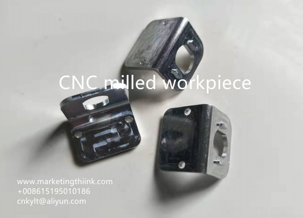
CNC milled workpiece

BLADE SLOT TYPE SELECTION

Use positive front angle slot indexable blade as much as possible to ensure smooth cutting action and minimum power consumption.

USE CORRECT FEED

By using the recommended maximum chip thickness, ensure the correct feeding of the blade to achieve the correct cutting effect.

CUTTING DIRECTION

Use milling as far as possible.

PART CONSIDERATIONS

Workpiece material and configuration, as well as the quality requirements of the surface to be processed.

BLADE MATERIAL SELECTION

Select groove type and material according to material type and application type of workpiece.
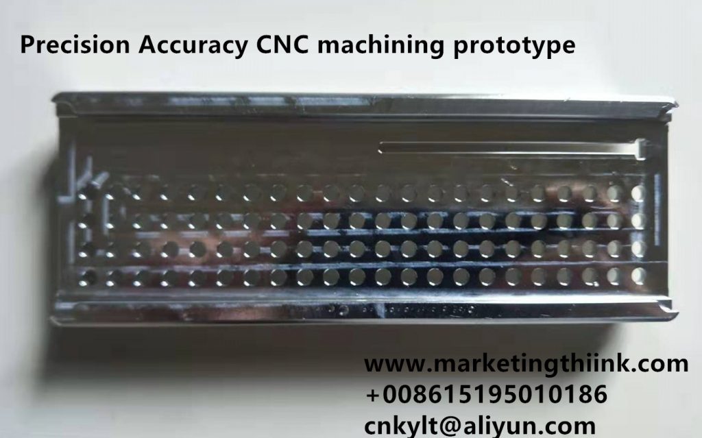
Precision Accuracy CNC machining prototype

VIBRATION DAMPING MILLING CUTTER

For a long overhang that is more than 4 times the tool diameter, the vibration trend will become more obvious, and the use of vibration damping tools can significantly improve the productivity.

MAIN DEFLECTION ANGLE

Select the most suitable main deflection angle.

MILLING CUTTER DIAMETER

Select the correct diameter according to the width of the workpiece.
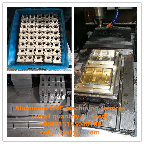
small order CNC machining service

POSITION OF MILLING CUTTER

Position the milling cutter correctly.

CUTTER CUT IN AND CUT OUT

It can be seen that through arc cutting, the chip thickness is always zero when the tool is withdrawn, so that higher feed and longer tool life can be achieved.

COOLANT

Use coolant only if necessary. In general, milling is better performed without coolant.

MAINTENANCE

Follow tool maintenance recommendations and monitor tool wear.
KYLT Precision CNC machining services (milling & turning service), Fast prototyping, Fixture/Jig/Tooling making, Aluminum die casting & plastic injection parts. Email:cnkylt@aliyun.com +008615195010186
KYLT CNC Machining Services:
KYLT CNC Precision Machined Parts:
More information about Machining Technology:

评论

此博客中的热门博文

SIMPLIFIED DRAWING METHOD FOR MECHANICAL DRAWING

When design  machine parts  /  prototypes  by 2D engineering method, we can adopt simplified drawing method: 1.When the object ( mechanical part ) has several identical structures (teeth, slots, etc.) and distributes according to certain rules, only a few complete structures need to be drawn. The rest are connected by fine lines, and the total number of structures is indicated. Mechanical part  Examples of Simplified Drawing of Mechanical Drawings : Examples of Simplified Drawing of Mechanical Drawings for Same Structure and Simplified Drawing Same Structure and Simplified Drawing 2.A number of holes with the same diameter and regular distribution (round holes, screw holes, sinks, etc.) can be drawn only one or several, the rest can only be represented by the center line, and the total number of holes should be indicated when the size of holes is marked in the figure. Simplified Drawing Method for Regularly Distributed Holes Simplified Drawing ...

WHY SCREW THREAD CAN NOT PASS THREAD GAUGE INSPECTION

After the first metal part be tapped, we always to check it: if pass the thread gauge inspection? The inspection result is OK, we can do mass production. If it fails, We should consider which reasons cause tapping faiulre. KYLT provide Metal Machining services for:  WEDM, EDM, DRILL, TAPPING ,  CNC LATHING ,  CNC MILLING ,  ALUMINUM / MAGNESIUM / PLASTIC RAPID PROTOTYPES MAKING . 1PCS ORDER IS ALLOWED. Aluminum CNC machined workpiece Normally, the following reasons may cause screw thread faiulre: 1) UNQUALIFIED TAP Tap is wear or bad 2) QUALIFIED DRILLING HOLE (BEFORE TAPPING) If the hole is too small, because of friction, will increase the difficulty of tapping, while tapping faster wear, and vice versa, the hole is too big, it can easily tap into, but the quality of teeth is very poor, because the diameter of teeth will become larger, relative to the screw nut bonding force is insufficient, easy to slide teeth. In M3 *0.5, the correct hole (general i...

CNC MILLING: DOWN MILLING &UP MILLING

CNC milling  process adopt  Down milling  or  Up milling ? Which milling method is better? Down Milling & Up Milling Definition Down milling:  refers to the cutting speed direction of the cutter is the same as the moving direction of the workpiece. Up milling : refers to the direction of cutting speed opposite to the direction of movement of the workpiece. CNC milling work, How to distinguish Down Milling and Up Milling. WHEN MILLING WORKPIECE OUTLINE: Clockwise feeding and programming along the outline of the workpiece is Down milling. Counterclockwise programming and feeding along the outline of the workpiece is Up milling. WHEN MILLING THE INNER CONTOUR OF THE WORKPIECE: Clockwise feeding and programming along the inner contour of the workpiece is downmilling. Counterclockwise programming and feeding along the inner contour of the workpiece is reverse milling. CNC UP & DOWN MILLING CHARACTERISTICS OF DOWN MILLING AND UP MILLI...