NPT, Pt, G are pipe threads
What is NPT screw thread?
NPT is the abbreviation of national (American) pipe thread, which belongs to 60 degree taper pipe thread of American Standard and is used in North America. Refer to GB / t12716 for national standard.
What is PT screw thread?
PT is the abbreviation of pipe thread. It is a 55 degree sealed tapered pipe thread, belonging to the Wyeth thread family. It is mostly used in European and Commonwealth countries. It is commonly used in the water and gas pipe industry. The taper is specified as 1:16. Refer to GB / t7306 for national standards.
What is G screw thread?
G is a 55 degree non thread sealing pipe thread, belonging to the Wyeth thread family. The mark g represents cylindrical thread. Refer to GB / t7307 for national standard.
In addition, 1 / 4, 1 / 2 and 1 / 8 marks in the thread refer to the diameter of the thread size, and the unit is inch. The insiders usually call the thread size by minute, one inch is equal to 8 minutes, one / 4 inch is 2 minutes, and so on.
G is the general designation of pipe thread (Guan). The division of 55 and 60 degrees is functional, commonly known as pipe circle. That is, the thread is processed from a cylindrical surface.
ZG is commonly known as pipe cone, that is, the thread is processed from a circular cone. The general water pipe joints are like this, and the national standard is marked RC.
What is Metric screw thread?
Metric threads are represented by pitch, while American and British threads are represented by the number of threads per inch, which is the biggest difference between them.
Metric thread is 60 degrees of equal profile, English thread is 55 degrees of equal waist profile, American thread is 60 degrees.
Metric screw threads are in metric units, and American and British screw threads are in English units.
THE PIPE THREAD
The pipe thread is mainly used for the connection of pipes. The internal and external threads are closely matched, including straight pipe and cone pipe. Nominal diameter refers to the diameter of the connected pipe. Obviously, the thread diameter is larger than the nominal diameter. 1 / 4, 1 / 2, 1 / 8 is the nominal diameter of inch thread.
ANGLE OF THREAD:
60 degrees for metric and American threads, 55 degrees for British system, 30 degrees for TM water pipe thread, 60 degrees for SM needle thread and BC thread, 30 degrees for metric trapezoidal thread, 29 degrees for British trapezoidal thread, and table thread (tw29 degrees TR and tm30 degrees).
COMMON THREAD:
metric thread M; British system w; American system UNC, une, UNEF
PIPE THREAD:
British PS, Pt, PF; American NPs, NPT, NPTF, NPSM
AIR NOZZLE THREAD:
The outer diameter of CTV and TV 1 / 4-20 is 1A: 0.2367-0.2489 (6.012-6.322); 2A: 0.2408-0.2489 (6.116-6.322) 3A: 0.2419-0.2500 (6.1443-6.350)
INCH THREAD:
according to nominal size and number of threads per inch
For example, 1 / 4 “- 20, 3 / 4” – 10, 1 “- 8, 1 / 4” – 20 means that the nominal size is 1 / 4, that is, the major diameter is 6.35mm (25.4 divided by 4 = 6.35), 20 teeth per inch, and so on.
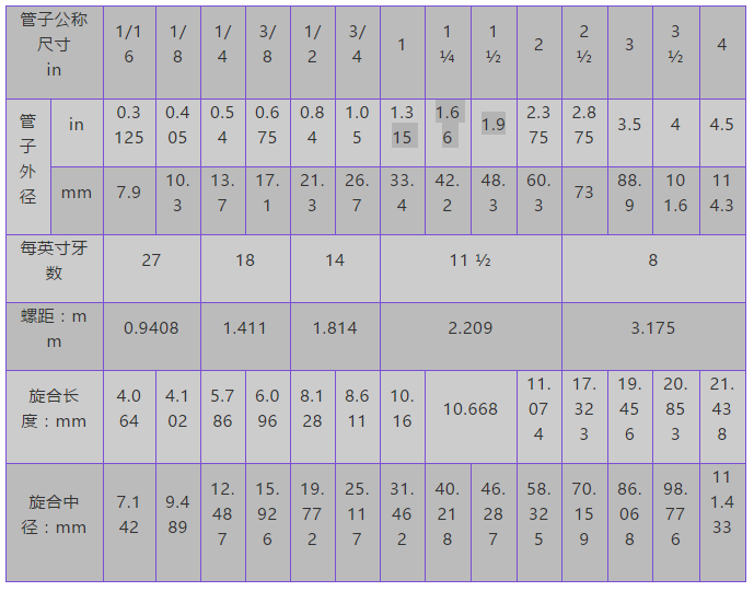
NPT THREAD BRIEF SIZE
KYLT Precision CNC machining services (milling & turning service), Fast prototyping, Fixture/Jig/Tooling making, Aluminum die casting & plastic injection parts. Email:cnkylt@aliyun.com +008615195010186
KYLT CNC Machining Services:
KYLT CNC Precision Machined Parts:
More information about Machining Technology:
评论
发表评论