跳至主要内容

DIE CASTING ALUMINUM POWER/ELECTRIC/HAND TOOLS PARTS

Aluminum power tool, electric tool, hand tool parts, which made by aluminum die casting method.
Pneumatic hand tool and electric hand tool most use aluminum die casting spare part as the aluminum have good mechanical function and low cost.
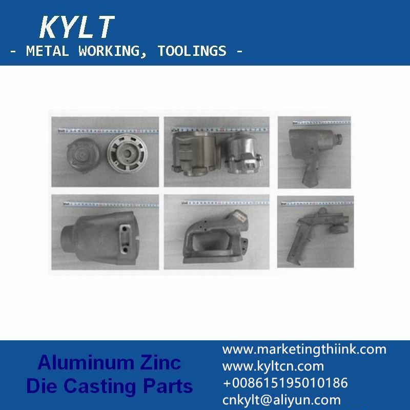
aluminum electric hand tool parts by die casting

What are the advantages of Die Casting method:

Pressure aluminum injection suitable for a range of metal alloys, die casting has the following advantages:
  • Saving cost, not only in the part price itself but also in the overall cost of production.
  • Produces complex parts to net shape, reducing secondary machining
  • High-speed production compared to other manufacturing processes
  • Die cast parts are durable and have a long service life
  • Produces components with attractive, high-quality surface finishes
  • Produces a broad range of shapes and surface textures
  • Variable wall thicknesses
  • Simplifies the assembly process by integrating fastening elements
  • Fewer steps from raw material to finished part
  • Tighter tolerances
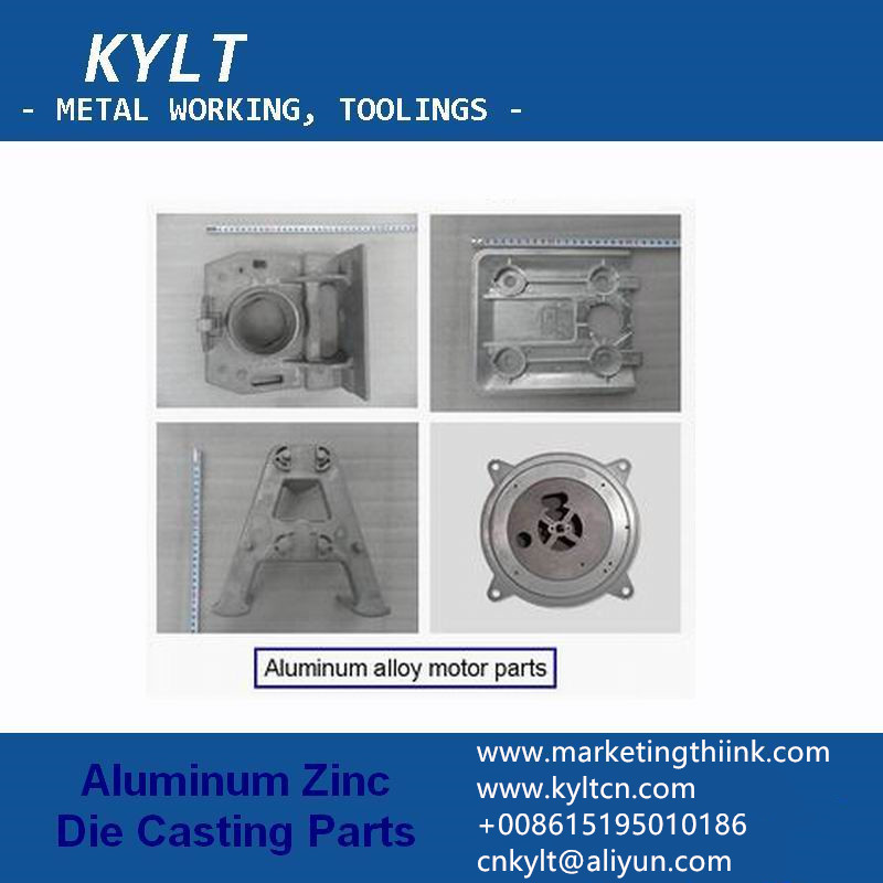
aluminum alloy motor parts by die casting
KYLT Precision CNC machining services (milling & turning service), Fast prototyping, Fixture/Jig/Tooling making, Aluminum die casting & plastic injection parts. Email:cnkylt@aliyun.com +008615195010186
KYLT CNC Machining Services:
KYLT CNC Precision Machined Parts:
More information about Machining Technology:

评论

此博客中的热门博文

SIMPLIFIED DRAWING METHOD FOR MECHANICAL DRAWING

When design  machine parts  /  prototypes  by 2D engineering method, we can adopt simplified drawing method: 1.When the object ( mechanical part ) has several identical structures (teeth, slots, etc.) and distributes according to certain rules, only a few complete structures need to be drawn. The rest are connected by fine lines, and the total number of structures is indicated. Mechanical part  Examples of Simplified Drawing of Mechanical Drawings : Examples of Simplified Drawing of Mechanical Drawings for Same Structure and Simplified Drawing Same Structure and Simplified Drawing 2.A number of holes with the same diameter and regular distribution (round holes, screw holes, sinks, etc.) can be drawn only one or several, the rest can only be represented by the center line, and the total number of holes should be indicated when the size of holes is marked in the figure. Simplified Drawing Method for Regularly Distributed Holes Simplified Drawing ...

WHY SCREW THREAD CAN NOT PASS THREAD GAUGE INSPECTION

After the first metal part be tapped, we always to check it: if pass the thread gauge inspection? The inspection result is OK, we can do mass production. If it fails, We should consider which reasons cause tapping faiulre. KYLT provide Metal Machining services for:  WEDM, EDM, DRILL, TAPPING ,  CNC LATHING ,  CNC MILLING ,  ALUMINUM / MAGNESIUM / PLASTIC RAPID PROTOTYPES MAKING . 1PCS ORDER IS ALLOWED. Aluminum CNC machined workpiece Normally, the following reasons may cause screw thread faiulre: 1) UNQUALIFIED TAP Tap is wear or bad 2) QUALIFIED DRILLING HOLE (BEFORE TAPPING) If the hole is too small, because of friction, will increase the difficulty of tapping, while tapping faster wear, and vice versa, the hole is too big, it can easily tap into, but the quality of teeth is very poor, because the diameter of teeth will become larger, relative to the screw nut bonding force is insufficient, easy to slide teeth. In M3 *0.5, the correct hole (general i...

CNC MILLING: DOWN MILLING &UP MILLING

CNC milling  process adopt  Down milling  or  Up milling ? Which milling method is better? Down Milling & Up Milling Definition Down milling:  refers to the cutting speed direction of the cutter is the same as the moving direction of the workpiece. Up milling : refers to the direction of cutting speed opposite to the direction of movement of the workpiece. CNC milling work, How to distinguish Down Milling and Up Milling. WHEN MILLING WORKPIECE OUTLINE: Clockwise feeding and programming along the outline of the workpiece is Down milling. Counterclockwise programming and feeding along the outline of the workpiece is Up milling. WHEN MILLING THE INNER CONTOUR OF THE WORKPIECE: Clockwise feeding and programming along the inner contour of the workpiece is downmilling. Counterclockwise programming and feeding along the inner contour of the workpiece is reverse milling. CNC UP & DOWN MILLING CHARACTERISTICS OF DOWN MILLING AND UP MILLI...