跳至主要内容

CNC MACHINING CENTER CUTTING PARAMETERS TABLE

CNC machining can be divided into two categories: ordinary machining and high-speed machining.
Ordinary machine generally refers to the machine tool with a revolution of less than 8000; high-speed machine generally refers to the machine tool with a revolution of more than 12000, and the machine tool between 8000 and 12000 is called quasi high-speed machine.
CNC machining process is usually divided into three categories: rough cutting, medium light (semi fine) and smooth cutter (fine milling). Generally speaking, it is better to use large cutter (flying cutter and end milling cutter) and large cutting depth and step (heavy cutting) for rough cutting, so as to remove materials quickly and in large quantities. In order to obtain the perfect surface accuracy, light cutting (small cutting depth, small step) with high speed and feed is used. End milling cutter (or fillet cutter) and flying cutter for smooth surface, end milling cutter for smooth vertical wall and ball cutter (or fillet cutter) for smooth surface.
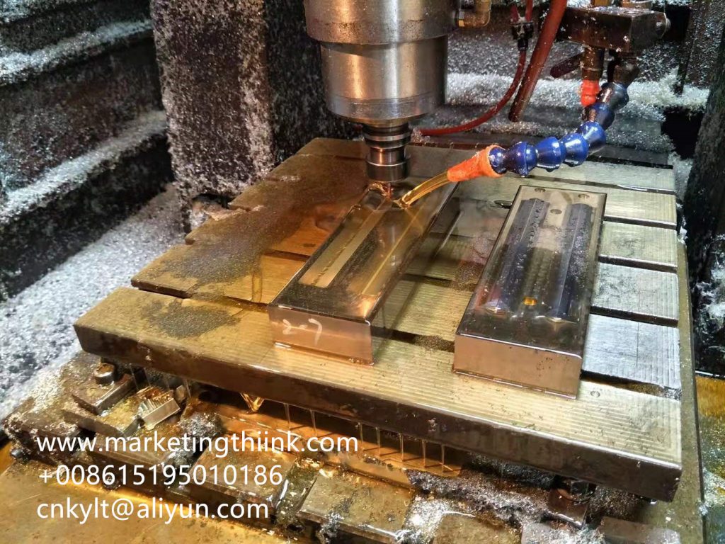
Aluminum part made by CNC milling
In the process of machining, appropriate cutting tools should be selected according to the material hardness of the parts to be processed, such as plastic, wood, etc. domestic white steel knives can be selected.
Copper, aluminum and steel with hardness less than 38 degrees Rockwell (such as 45 steel and trump material) shall be imported steel knives and domestic high-quality steel knives. For materials with high hardness (such as hardened die steel), alloy knife, titanium plated knife or tungsten steel knife should be preferred.
In this paper, some cutting parameters of popular CNC machining center are provided for reference. Various kinds of cutting tools (flying knife, white steel, end milling cutter, tungsten steel flat milling cutter, white steel ball cutter, tungsten steel ball cutter) are described respectively for roughening and smooth cutter. Due to the large number of workpiece materials, this table only describes the representative aluminum alloy, 45 steel and stainless steel.

Tool cutting parameter table 1

THROWING KNIFE, ROUGH CUT, 45 STEEL
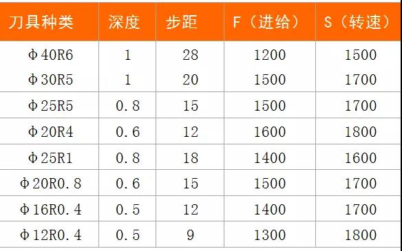
Tool cutting parameter table I
Tool cutting parameter table 1

Cutting Parameters Table 2

IMPORTED WHITE STEEL FLAT BLADE, ROUGH CUTTING, ALUMINUM ALLOY, 45 STEEL
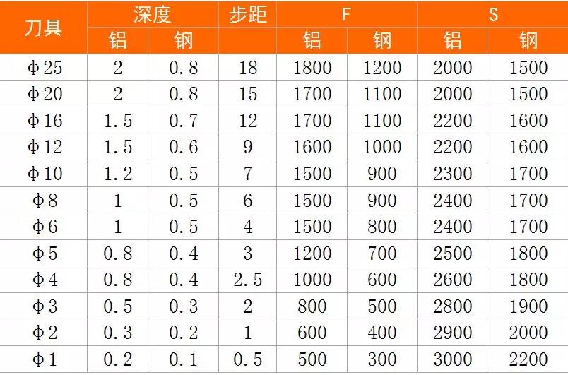
Cutting Parameters Table II
Cutting Parameters Table 2

Cutting parameters table 3

WHITE STEEL BALL KNIFE, SMOOTH KNIFE, ALUMINUM ALLOY, 45 STEEL
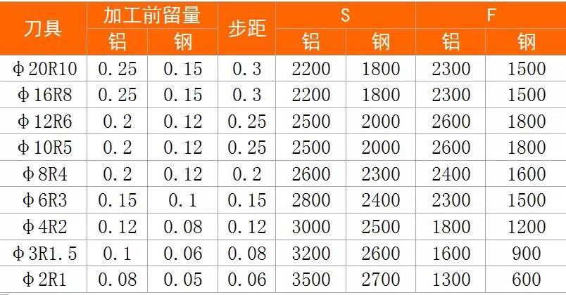
Cutting parameters table 4

TUNGSTEN STEEL BALL KNIFE, SMOOTH, 45 STEEL, STAINLESS STEEL
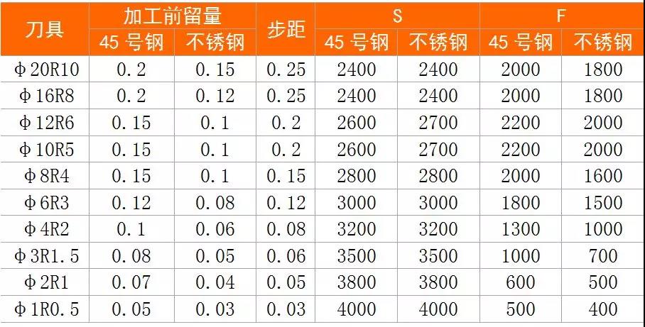
Cutting parameters table 4

Cutting parameters Table 5

TUNGSTEN STEEL FLAT KNIFE, SMOOTH KNIFE, 45 STEEL, STAINLESS STEEL
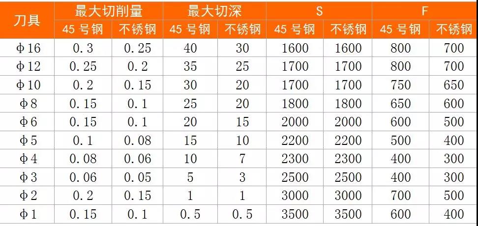
Cutting parameters Table 5

Cutting parameters Table 6

WHITE STEEL FLAT KNIFE, SMOOTH KNIFE, ALUMINUM ALLOY, 45 STEEL
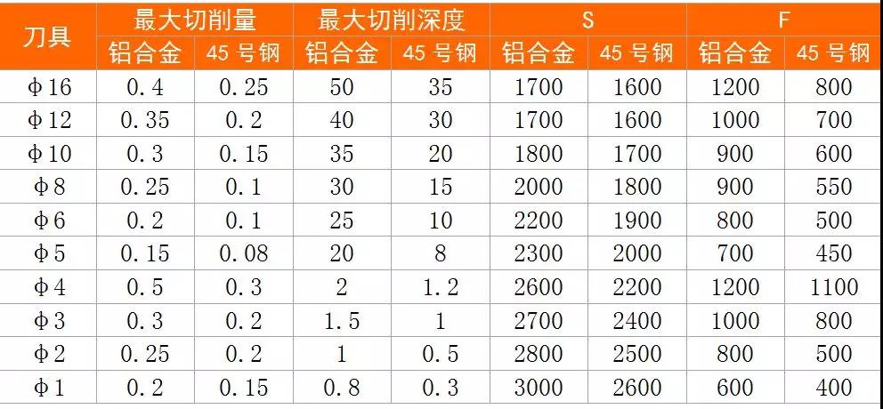
Cutting parameters Table 6
KYLT Precision CNC machining services (milling & turning service), Fast prototyping, Fixture/Jig/Tooling making, Aluminum die casting & plastic injection parts. Email:cnkylt@aliyun.com +008615195010186
KYLT CNC Machining Services:
KYLT CNC Precision Machined Parts:
More information about Machining Technology:

评论

此博客中的热门博文

WHY SCREW THREAD CAN NOT PASS THREAD GAUGE INSPECTION

After the first metal part be tapped, we always to check it: if pass the thread gauge inspection? The inspection result is OK, we can do mass production. If it fails, We should consider which reasons cause tapping faiulre. KYLT provide Metal Machining services for:  WEDM, EDM, DRILL, TAPPING ,  CNC LATHING ,  CNC MILLING ,  ALUMINUM / MAGNESIUM / PLASTIC RAPID PROTOTYPES MAKING . 1PCS ORDER IS ALLOWED. Aluminum CNC machined workpiece Normally, the following reasons may cause screw thread faiulre: 1) UNQUALIFIED TAP Tap is wear or bad 2) QUALIFIED DRILLING HOLE (BEFORE TAPPING) If the hole is too small, because of friction, will increase the difficulty of tapping, while tapping faster wear, and vice versa, the hole is too big, it can easily tap into, but the quality of teeth is very poor, because the diameter of teeth will become larger, relative to the screw nut bonding force is insufficient, easy to slide teeth. In M3 *0.5, the correct hole (general i...

SIMPLIFIED DRAWING METHOD FOR MECHANICAL DRAWING

When design  machine parts  /  prototypes  by 2D engineering method, we can adopt simplified drawing method: 1.When the object ( mechanical part ) has several identical structures (teeth, slots, etc.) and distributes according to certain rules, only a few complete structures need to be drawn. The rest are connected by fine lines, and the total number of structures is indicated. Mechanical part  Examples of Simplified Drawing of Mechanical Drawings : Examples of Simplified Drawing of Mechanical Drawings for Same Structure and Simplified Drawing Same Structure and Simplified Drawing 2.A number of holes with the same diameter and regular distribution (round holes, screw holes, sinks, etc.) can be drawn only one or several, the rest can only be represented by the center line, and the total number of holes should be indicated when the size of holes is marked in the figure. Simplified Drawing Method for Regularly Distributed Holes Simplified Drawing ...

CNC MILLING: DOWN MILLING &UP MILLING

CNC milling  process adopt  Down milling  or  Up milling ? Which milling method is better? Down Milling & Up Milling Definition Down milling:  refers to the cutting speed direction of the cutter is the same as the moving direction of the workpiece. Up milling : refers to the direction of cutting speed opposite to the direction of movement of the workpiece. CNC milling work, How to distinguish Down Milling and Up Milling. WHEN MILLING WORKPIECE OUTLINE: Clockwise feeding and programming along the outline of the workpiece is Down milling. Counterclockwise programming and feeding along the outline of the workpiece is Up milling. WHEN MILLING THE INNER CONTOUR OF THE WORKPIECE: Clockwise feeding and programming along the inner contour of the workpiece is downmilling. Counterclockwise programming and feeding along the inner contour of the workpiece is reverse milling. CNC UP & DOWN MILLING CHARACTERISTICS OF DOWN MILLING AND UP MILLI...