Heat treatment always used in steel iron metal parts to improve the hardness, to get quality machined parts which met mechanical design requirement.
Heat treatments functions:
- improving the mechanical properties of materials
- eliminating residual stress
- improving the machinability of metals.
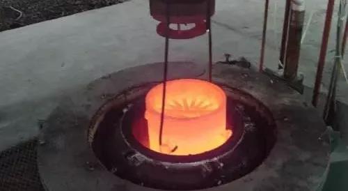
According to different purposes, heat treatment process can be divided into two categories: preparatory heat treatment and final heat treatment.
1.PREPARATORY HEAT TREATMENT
The purpose of preparing heat treatment is to improve processing performance, eliminate internal stress and prepare good metallographic structure for final heat treatment. Its heat treatment process includes annealing, normalizing, aging, tempering and so on.
1) ANNEALING AND NORMALIZING
Annealing and normalizing are used for hot-worked blanks. Carbon steel and alloy steel with carbon content more than 0.5% are usually annealed to reduce their hardness and easy to cut. Carbon steel and alloy steel with carbon content less than 0.5% are normalized to avoid sticking knife when their hardness is too low. Annealing and normalizing can refine the grain size and homogenize the structure, so as to prepare for the subsequent heat treatment. Annealing and normalizing are usually arranged after the blank is manufactured and before rough machining.
2) AGING TREATMENT
Aging treatment is mainly used to eliminate the internal stress in blank manufacturing and machining.
In order to avoid excessive transportation workload, for parts with general accuracy, one aging treatment can be arranged before finishing. However, for parts with high precision (such as the box of coordinate boring machine, etc.), two or several aging processes should be arranged. Simple parts are generally not aged.
In addition to castings, for some precision parts with poor rigidity (such as precision lead screw), in order to eliminate the internal stress generated in machining and stabilize the processing accuracy of parts, multiple aging treatments are often arranged between rough and semi-finish machining. For some shaft parts, aging treatment should be arranged after straightening process.
3) CONDITIONING
Tempering is to temper at high temperature after quenching. It can obtain uniform and fine tempered sorbite structure and prepare for reducing deformation during subsequent surface quenching and nitriding treatment. Therefore, tempering can also be used as preparatory heat treatment.
Because of the good comprehensive mechanical properties of quenched and tempered parts, some parts with low hardness and wear resistance requirements can also be used as the final heat treatment process.
2. FINAL HEAT TREATMENT
The ultimate purpose of heat treatment is to improve mechanical properties such as hardness, wear resistance and strength.
1) QUENCHING
Quenching includes surface quenching and overall quenching. Surface quenching is widely used because of its small deformation, oxidation and decarbonization, and it also has the advantages of high external strength, good wear resistance, good toughness and strong impact resistance. In order to improve the mechanical properties of surface hardened parts, heat treatment such as quenching or normalizing is often required as a preparatory heat treatment.
Its general technological route is: blanking – forging – normalizing (annealing) – Roughing – tempering – semi – finishing – surface quenching – finishing.
2) CARBURIZING AND QUENCHING
Carburizing quenching is suitable for low carbon steel and low alloy steel. First, the carbon content of the surface layer of the parts is increased. After quenching, the surface layer achieves high hardness, while the core still maintains a certain strength and high toughness and plasticity. Carburizing can be divided into whole carburizing and partial carburizing. When carburizing locally, anti-seepage measures (copper plating or anti-seepage material plating) should be taken for the non-carburized part. Because of the large deformation of carburizing and quenching, and the depth of carburizing is generally between 0.5 and 2 mm, the carburizing process is generally arranged between semi-finishing and finishing.
Its technological route is generally as follows: blanking – forging – normalizing – rough, semi-finishing – carburizing quenching – finishing.
When the non-carburized part of the carburized part of the local authorities adopts the technological scheme of removing the redundant carburized layer after increasing the allowance, the process of removing the redundant carburized layer should be arranged after carburizing and before quenching.
3) NITRIDING TREATMENT
Nitriding is a method to make nitrogen atom infiltrate into metal surface to obtain a layer of nitrogen compounds. Nitriding layer can improve the hardness, wear resistance, fatigue strength and corrosion resistance of parts surface. Because the nitriding treatment temperature is low, the deformation is small, and the nitriding layer is thin (generally not more than 0.6-0.7 mm), the nitriding process should be arranged as far back as possible. In order to reduce the deformation during nitriding, high temperature tempering after cutting is generally required to eliminate stress.
KYLT Precision CNC machining services (milling & turning service), Fast prototyping, Fixture/Jig/Tooling making, Aluminum die casting & plastic injection parts. Email:cnkylt@aliyun.com +008615195010186
KYLT CNC Machining Services:
KYLT CNC Precision Machined Parts:
More information about Machining Technology:
评论
发表评论