Classification according to the control track of CNC machine tool movement.
(1) CNC machine tool controlled by point and position
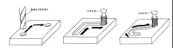
Point position control requires to control the moving parts to move from one point to another for accurate positioning. The requirements for the motion track between points are not strict. In the process of moving, there is no processing, and the motion between the coordinate axes is irrelevant. In order to achieve fast and accurate positioning, the movement of displacement between two points generally moves fast first. And then approaches the positioning point slowly to ensure the positioning accuracy. As shown below, which is the motion track controlled by the point position.
The machine tools with point control function mainly include CNC drilling machine, CNC milling machine, CNC punch, etc. With the development of numerical control technology, there are few numerical control systems which are only used for point control.
(2) linear control CNC machine tool
Linear control CNC machine tool is also called parallel control CNC machine tool. It is characterized by not only the accurate positioning between control points, but also the movement speed and route (track) between two related points. However, its movement route is only parallel to the coordinate axis of the machine tool. That is to say, only one coordinate axis is controlled at the same time. In the process of shifting, the tool can cut at the specified feed speed. Generally only rectangular and stepped parts can be machined.
The machine tools with linear control function mainly include relatively simple CNC lathe, CNC milling machine, CNC grinding machine, etc. The numerical control system of this machine tool is also called linear control numerical control system. Similarly, there are few CNC machine tools which are only used for linear control.
(3) contour control CNC machine tool
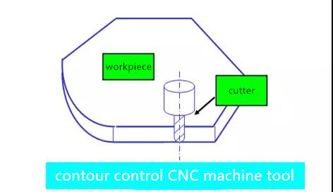
Contour control CNC machine tool is also called continuous control CNC machine tool. It can control the displacement and speed of two or more motion coordinates at the same time.
In order to meet the requirements of the relative movement path of the tool along the workpiece contour. The displacement control and speed control of each coordinate motion must be accurately coordinated according to the specified proportional relationship.
Therefore, in this kind of control mode, the CNC device is required to have the function of interpolation operation. Interpolation is to describe the shape of a line or an arc according to the basic data input by the program, through the mathematical processing of the interpolation arithmetic in the CNC system. While calculating, pulses are distributed to the controllers of each coordinate axis according to the calculation results, so as to control the linkage displacement of each coordinate axis. Consistent with the required contour, the tool can continuously cut the workpiece surface in the process of movement. It can process all kinds of straight lines, arcs and curves.
This kind of machine tools mainly include: CNC lathe, CNC milling machine, CNC wire cutting machine, machining center, etc. The corresponding CNC device is called contour control CNC system, which can be divided into the following forms according to the number of linkage coordinate axes it controls:
1.TWO AXIS LINKAGE:
it is mainly used for CNC lathe to process rotating surface or CNC milling machine to process curve cylinder surface.
2. TWO-AXIS SEMI LINKAGE:
it is mainly used for the control of machine tools with more than three axes, two of which can be linked, and the other one can be used for periodic feeding.
3. THREE AXIS LINKAGE:
generally, it can be divided into two types:
one is x / Y / Z three linear coordinate axis linkage, which is widely used in CNC milling machine, machining center, etc.;
the other is to control not only two linear coordinates in X / Y / Z, but also the rotation coordinate axis revolving around one of the linear coordinate axes.
For example, in the turning center, in addition to the longitudinal (Z-axis) and transverse (x-axis) two linear coordinate axes linkage. It also needs to control the spindle (c-axis) linkage around the z-axis rotation at the same time.
4.FOUR AXIS LINKAGE:
simultaneously control X / Y / Z three linear coordinate axes and a rotation coordinate axis linkage.
5.FIVE AXIS LINKAGE:
In addition to controlling the linkage of three X / Y / Z axis, it also controls two coordinate axes of A, B and C axis rotating around these linear coordinate axes, forming the simultaneous control of five axis linkage. At this time, the tool can be set in any direction of space.
For example, control the cutter to swing around the x-axis and y-axis at the same time, so that the cutter always maintains the normal direction with the machined contour surface on its cutting point, so as to ensure the smoothness of the machined surface, improve its machining accuracy and efficiency, and reduce the roughness of the machined surface.
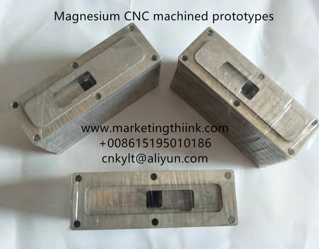
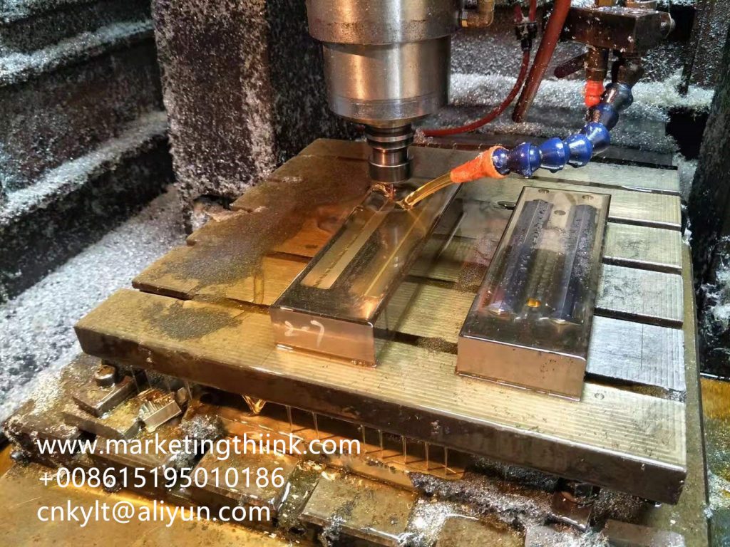
KYLT Precision CNC machining services (milling & turning service), Fast prototyping, Fixture/Jig/Tooling making,Aluminum die casting & plastic injection parts. Email:cnkylt@aliyun.com +008615195010186
KYLT CNC Machining Services:
KYLT CNC Precision Machined Parts:
More information about Machining Technology:
评论
发表评论